
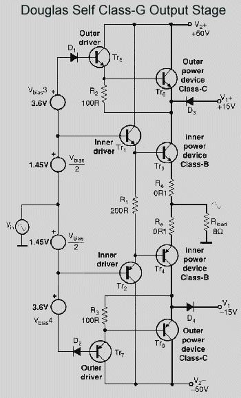
 | The Class-G Power AmplifierClass-G amplifiers are now gaining greater acceptance than ever before, due to their high efficency. However, reservations about their distortion performance have often been expressed. Douglas Self's innovative design removes the compromises and shows linearity approaching that of his other designs. |
Music has a large peak-to-mean level ratio. The power output is usually a long way below the peak levels, and this is what makes possible the improved efficiency of Class-G. Power is drawn from either high or low-voltage rails as the signal level demands, and for most of the time the output transistors are supplied from the low-voltage rails, so there is a low voltage drop between supply rail and the output, and correspondingly low dissipation. On the occasional signal peaks, the amplifier draws its power from the high-voltage rails. In previous designs the transfer from rail to rail has caused output glitches; this problem is solved in the Douglas Self Class-G power amplifier by some innovative and authoritative design, including the use of Schottky diodes to eliminate carrier-storage glitching.
The amplifier and the design philososphy behind it was described in detail in Electronics World for December 2001 and Jan 2002. The PCB includes the Class-G mode indicator described in the Feb 2002 article.
This amplifier is particularily suitable for driving sub-woofers, or the low-frequency units in multi-amped systems. Its performance is far superior to the Class-D amplifiers sometimes used for this task, giving lower noise, much lower distortion, and an efficiency with real signals that is almost as good.
 |
|
PCB 005: £35.00 |
![]()
 |
S P E C I F I C A T I O N S
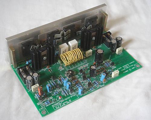
P C BThe Class-G amplifier PCB is produced to the highest standards:
|
![]()
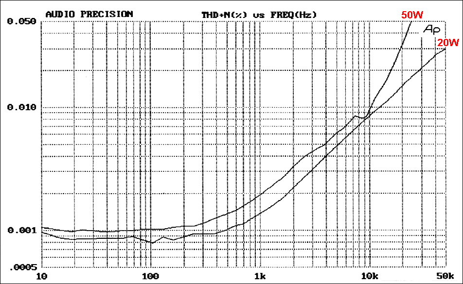 | This graph shows the typical amplifier THD at 20W/8R and 50W/8R when running from a lower supply rail of +/-25V and an upper supply rail of +/-40V. Performance at higher supply rails is slightly improved.
Measurement system Audio Precision System-1. Please note that the dip in the distortion curve around 8 kHz for the 50W case is not evidence of glitching; it is due to a fortuitous cancellation of distortion harmonics. |