
| The Load-Invariant Power Amplifier: 2.0
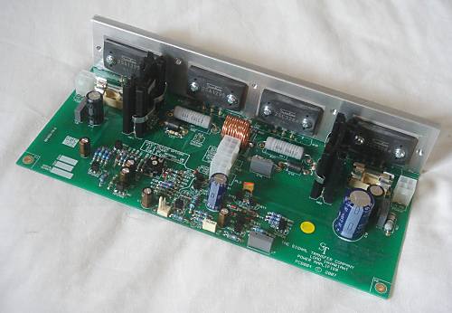
The Load-Invariant Power Amplifier PCB has been redesigned to use the latest output transistors in either TO3P or MT-200 packages. There have been many other improvements; see below.
|
A Load-Invariant power amplifier is one that is specially designed to give exceptional linearity into low impedances. The ultimate aim- for perfect Load Invariance- is a distortion performance that does not worsen at all as the load impedance falls from 8 Ohms to 4 Ohms and below. No amplifier currently exists that is perfectly Load Invariant, but in this design Douglas Self approaches closely to the ideal
One of the ways in which Load Invariance is improved is by the use of multiple output devices with carefully-chosen characteristics. This technique has the great advantage that it also reduces the crossover discontinuity for operation into loads of 8 Ohm or less, reducing the distortion produced. The Load Invariant amplifier therefore gives superior performance into 8 Ohms as well as 4 Ohms.
|
|
|
- Exceptionally low distortion into a wide range of load impedances.
- Very low noise, due to innovative feedback design.
- Unique enhanced-tempco bias generator gives excellent control of the critical quiescent conditions.
- Operates to full specification over a wide range of supply voltages without modification.
PCB 004: Ł35:00 each.
|
F EA T U R E S
- Output devices can be either TO3P or the larger MT200 package.
- Alternate positions are provided for the input transistors (Q1,Q2 or Q101,Q102) so that devices with differing pin-outs may be used without having to cross their legs.
- Tall components have been placed so as not to obstruct screwdriver access when mounting the output devices.
- Pads and tracking for a heatsink-mounted thermistor have been included. This will connect directly to the Signal Transfer Protection PCB.
- Full overload and short-circuit protection.
- Mechanical fixing arrangements improved.
- Comprehensive project notes included. The overlay includes mechanical dimensions for machining from flat bar an aluminium block for mounting the output devices.
- Optional input bootstrapping to raise input impedance.
- No hard-to-get components.

 |
| P C B
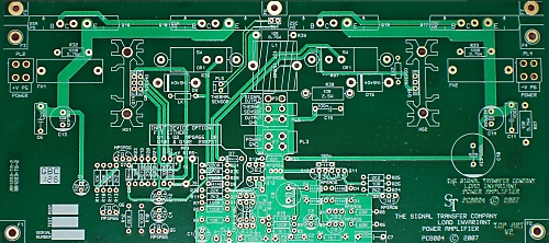
The PCB is now double-sided PTH, so wire links have been eliminated.
- All transistor positions have emitter, base and collector marked on the top-print to aid fault-finding.
- Board fixing holes and pads provided for easy mounting of TO3P output devices to a heatsink.
- High-quality double-sided plated-through-hole PCB
- Gold-plated pads
- Solder mask both sides, full screen print with component values included on the silk screen to aid assembly.
- Double-thickness 2-oz copper to minimise ground resistance and voltage drops.
- Wire connection points can be either via connectors or by direct soldering.
- Fully RoHS compliant.
- The form-factor of the PCB has been altered so that two will fit side by side in a 19" rack chassis.
- Board size 220 by 100 mm overall.
|
S P E C I F I C A T I O N S
- Power output: from 25W to 100W into 8 Ohms, depending on supply voltage. Assumes adequate heatsink.
- Power supply: +/-24V to +/-45V *
- Distortion: Less than 0.0008% at 1kHz, 25W/8R. Less than 0.004% at 10kHz, 25W/8R.
- Noise out: Less than -95 dBu (22-22kHz bandwidth, RMS, source resistance 50R)
- Gain: 23 times (+27.2 dB)
- Frequency response: +/-0.1 dB, 10Hz - 20kHz
- Input impedance: 2.2k without bootstrapping, 10k with bootstrapping option
* The Load Invariant PCB will operate correctly, in that it gives a visually undistorted sinewave output, from supply rails of +/-5V or lower. This means that initial testing can be done at minimal risk by slowly winding up a variable mains transformer. The amplifier will not of course meet its full performance specifications at such a low voltage.
 |
| This graph shows the typical amplifier THD when running from +/-24V minimum supply rails. Performance at higher supply rails is somewhat improved.
Measurement system: Audio Precision SYS-2702. Measurement bandwidth 80 kHz, RMS sensing.
|
