

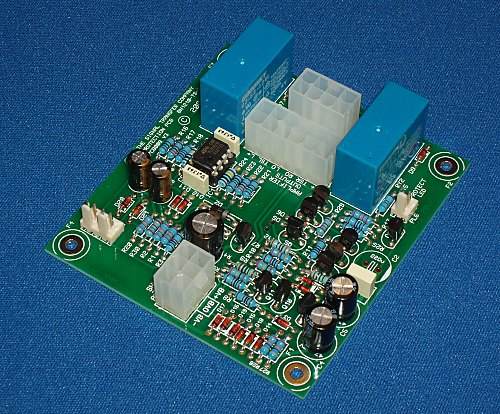
| The Amplifier/Speaker Protection PCB.
PCB008
|
It is always dangerous to connect a DC-coupled amplifier to a loudspeaker without proper protection against a DC fault. Such faults can not only destroy an expensive loudspeaker in a second, but may also present a safety hazard as the speaker coil suffers catastrophic overheating and catchs fire.
The Signal Transfer Company Protection PCB can be added simply to almost any amplifier system, providing safety against excess DC-offsets, and also over-temperature conditions and turn-on/turn-off transients. The PCB is designed to run directly from the power amplifier supply rails, accepting a very wide range of voltages; no additional power supply is required. Special circuitry is used to accelerate relay drop-out when an error occurs.
|
|
- Two channels of relay protection against excessive DC offsets. Both positive and negative error voltages are detected symmetrically. Separate relays are provided for each channel so high-current single-changeover types can be used.
- Slow turn-on to allow amplifier to settle before the speakers are connected.
- Fast-off on mains failure or switch-off, to prevent turn-off transients reaching the speakers. This can be disabled if your mains supply is subject to serious dips or brief interruptions.
- Two channels of over-temperature detection
- Immediate shutdown input
- Output for status LED
- Has on-board supply regulation and is suitable for any HT voltage between +/-25 V and +/-45 V
|
C O N N E C T I O N S
- The amplifier outputs are simply connected through the relays on this card to the output terminals
This also makes the connections to the DC offset detect circuitry
- Two connections to the low-voltage AC supply are made to drive the loss-of-AC detector
- Two 2-way connectors are provided for wiring to two thermistors for over-temperature detection
If only one temp detect point is required, the unused connector is shorted
- The shutdown pin is simply grounded to 0V to give immediate muting
- One 2-way connector for status LED
- Three power supply connections

S P E C I F I C A T I O N S
- Supply voltage: dual rail, from +/-25V to +/-45V.
- Turn-on delay: 3.0 Seconds +/-10%
- Turn-off time: Less than 1 msec (not including relay mechanical drop-out time)
- DC offset detect threshold: +/-2.0V
- Temperature cutout threshold: 87 degC (using recommended PTC thermistor EPCOS B59901D90A40)
- Relay type: 24V 1C/O
- Max relay coil current: 35 mA at 24V
- High-quality double-sided PCB, roller-tinned with solder mask and full screen print. Board size 78 by 89 mm
- Four fixing holes provided for simple mounting
Most of the operational parameters can be modified by changing component values. For example, the turn-on delay can be altered by using a different value of timing capacitor. Full details are given in the constructional notes supplied with the PCB.
Note: This unit does not give protection against overload or short-circuiting of a power amplifier output. In the case of Signal Transfer designs, overload protection is provided on the power amplifier card.